




Pneumatic Conveying System: How to Choose and Size One


Pneumatic Conveying System: How to Choose and Size One
A conveying line gets installed, runs fine on Monday, and by Friday the hopper is full of flaky tails and the elbow nearest the receiver has a hole worn clean through. Or the line simply will not keep up: the press starves every forty minutes and nobody can say whether it’s the blower, the pipe, or the material. Almost always, a pneumatic conveying system failed on a number nobody wrote down at the design stage.
Specifying one comes down to five figures: conveying velocity, solids loading ratio, equivalent length, available pressure, and what the air does to your resin on the way. Get those five right and the line is boring — which is exactly what you want from a pipe that has to work 24 hours a day.

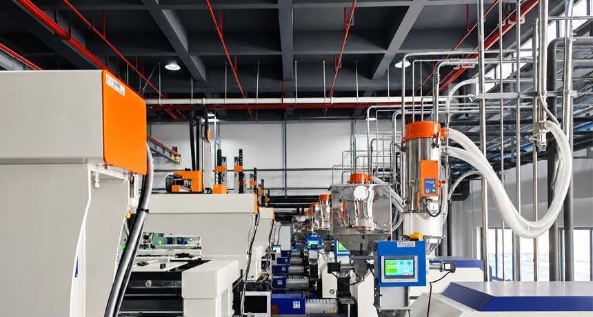
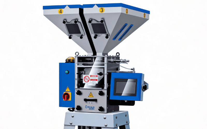
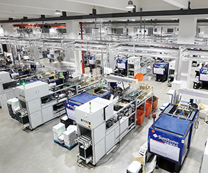
An integrated suction loading system: one receiver per material, sequenced by the central control panel.
>The Two Modes: Dilute Phase and Dense Phase
Every pneumatic conveying system moves material with air, but there are two fundamentally different ways to do it, and choosing between them is the first decision:
| Parameter | Dilute phase | Dense phase |
|---|---|---|
| How material moves | Suspended, flying in the air stream | As plugs or strands pushed along the pipe |
| Air velocity | 18–30 m/s | 2–10 m/s |
| Solids loading ratio (material:air by mass) | 2–15 | 20–100+ |
| Available pressure | 0.3–1.0 bar | 2–6 bar |
| Wear and material damage | Higher | Lower |
| Typical use in plastics | Pellets, standard plant conveying | Fragile, abrasive, or very fine powders |
For virgin pellets, dilute phase is the default and almost always the right answer — it’s simpler, cheaper, and forgiving. Dense phase earns its cost when the material is friable, abrasive, or so fine that high velocity turns it into dust, or when you must convey a long distance without shredding the product.
Conveying Velocity: The Number That Decides Everything
Two velocities bracket the design:
- Pickup velocity — the minimum air speed that lifts particles off the bottom of the pipe and keeps them moving. For plastic pellets this is roughly 15–18 m/s.
- Saltation velocity — the speed at which particles begin to drop out and settle in horizontal runs. Below it, material accumulates until the line plugs.
Design above both, but not far above. Sizing “to be safe” at 35 m/s is the single most common way plants manufacture their own quality problems:
- Angel hair and streamers. Soft pellets (LDPE, PP) scrape along the pipe wall at high speed and smear into tails that jam feed throats and block screens.
- Fines and dust. Every extra metre per second grinds a little more material into dust that ends up in filters and, eventually, on your parts.
- Power. Pressure drop rises roughly with the square of velocity — a line designed 30% faster than it needs can cost noticeably more to run for its whole life.
Practical target for pellets: 20–25 m/s at the pickup point, and check the velocity at the end of the line too — air expands as pressure drops, so velocity is highest where pressure is lowest.
Throughput: Solids Loading Ratio and Pipe Size
The core relationship is simple:
Throughput (kg/h) = air mass flow (kg/h) × solids loading ratio (SLR)
Which means pipe diameter and velocity together set the capacity. At a design velocity of 22 m/s and an SLR of 4 — a realistic figure for a vacuum dilute-phase pellet line — the capacity falls out like this:
| Pipe ID | Air volume @ 22 m/s | Air mass flow | Pellet capacity @ SLR 4 |
|---|---|---|---|
| 40 mm | 1.7 m³/min | ~120 kg/h | ~480 kg/h |
| 50 mm | 2.6 m³/min | ~187 kg/h | ~750 kg/h |
| 60 mm | 3.7 m³/min | ~270 kg/h | ~1,080 kg/h |
| 80 mm | 6.6 m³/min | ~477 kg/h | ~1,900 kg/h |
| 100 mm | 10.4 m³/min | ~746 kg/h | ~3,000 kg/h |
These are planning figures at roughly ambient suction conditions (air ≈ 1.2 kg/m³), not guarantees — material shape, pipe roughness, and line layout all move them. Use them to sanity-check a quotation: if a supplier promises 2,000 kg/h through a 50 mm line, ask to see the velocity.
Equivalent Length: Bends and Lift Eat Your Pressure Budget
A blower doesn’t see metres of pipe, it sees pressure drop. The useful way to think about layout is equivalent length — straight pipe plus a penalty for everything that disturbs the flow:
- 90° bends: plan on each bend costing the equivalent of roughly 5–8 m of straight pipe. A line with ten elbows carries the pressure penalty of an extra 60 m.
- Bend radius: short-radius elbows are the worst offenders for both pressure loss and material damage. Specify long-radius bends of at least 10–15 × pipe diameter wherever the layout allows.
- Vertical lift: a metre of vertical run costs roughly twice what a metre of horizontal run does.
Then check the total against what your air mover can actually deliver. Most dilute-phase pellet systems run on 0.3–1.0 bar. If your layout needs more than about 1 bar, you are out of dilute-phase territory: split the line into stages, or move to dense phase. As a rough planning guide, single-stage vacuum conveying handles runs on the order of 60–120 m; positive-pressure dilute systems go considerably further before they need staging.
Choosing the Air Mover
The air mover is the heart of any pneumatic conveying system — it sets the pressure available, and therefore how much equivalent length and how much material the line can carry at all. Pick it last, but only after the layout is quantified:
| Air mover | Typical pressure | Best for | Watch out for |
|---|---|---|---|
| Roots blower (positive pressure) | up to ~1 bar(g) | Long runs, high throughput, multiple receivers | Discharge air is hot — see below |
| Vacuum pump (rotary vane / claw) | −0.4 to −0.7 bar | Multiple pickup points feeding one source | Filter condition decides real capacity |
| Regenerative / side-channel blower | −0.2 to −0.3 bar | Short single-loader runs | Limited distance and rate |
| Compressed air (venturi / blow-through) | Plant air | Small, occasional transfers | Typically 3–5× the energy per kg conveyed |
Two habits worth breaking. First, running the line on plant compressed air because “the air is already there” — it is the most expensive kilogram of material you will ever move. Second, ignoring blower discharge temperature: a Roots blower can deliver air at 60–90°C, hot enough to soften pellet surfaces on the way and start the streamers you were trying to avoid. Put the blower on the suction side of the system, or add an aftercooler.
One genuine advantage of vacuum: leaks pull air in rather than pushing resin out. For most plastics plants, vacuum conveying is the cleaner and more forgiving choice — which is why machine-side receivers and plastic vacuum loaders dominate at the press.
What Conveying Does to the Material
The pipe is not neutral. It changes the resin on the way, and each of these is a specification decision:
- Angel hair and streamers — soft pellets at high velocity through tight bends. Fix with lower velocity, long-radius bends, and a larger pipe.
- Fines from regrind — regrind arrives with dust already in it and generates more. Conveying it through the same line as virgin resin contaminates the virgin stream; either separate the lines or accept the blend and control it downstream.
- Abrasion from glass-filled and mineral-filled grades — bends wear through first. Specify wear-resistant or replaceable bends on abrasive lines and inspect them on a schedule, not after they leak.
- Segregation of blends — masterbatch and virgin pellets can separate over long runs, so colour drifts between first-off and end-of-run parts. Keep runs short after dosing, or dose at the machine.
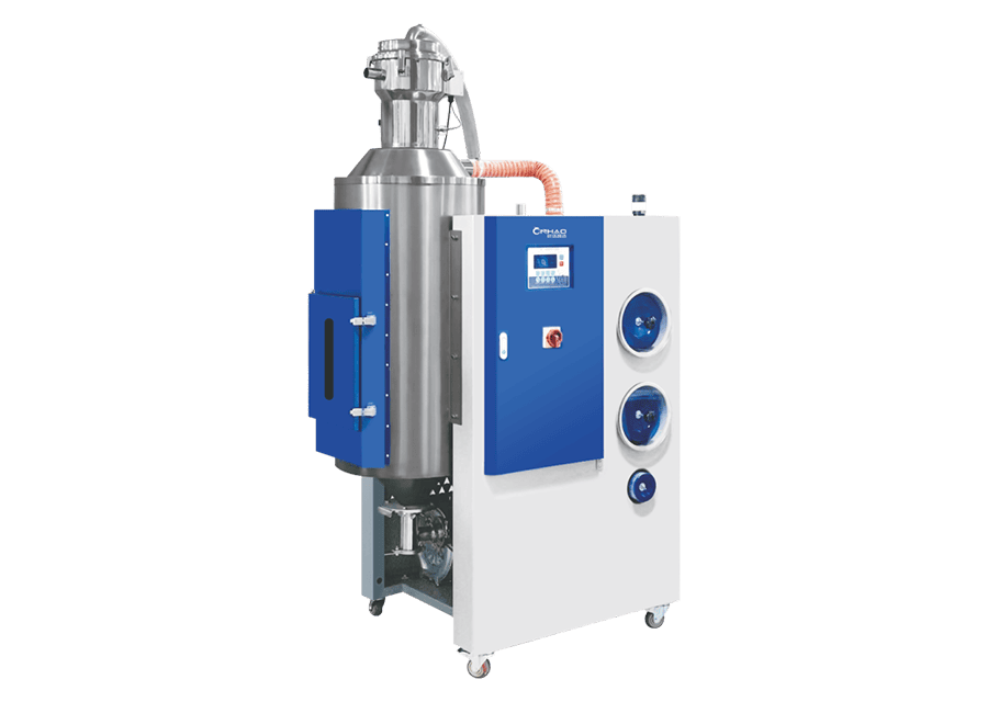
- Moisture — plant conveying air is ambient air. Conveying wet air through dried resin undoes part of the drying; for hygroscopic resins, dry after conveying or use dry conveying air. Our plastic dehumidifying dryer guide covers the dew-point side of that problem.
Feeding the Line: Airlocks, Receivers and Where the Material Comes From
A pneumatic conveying system is only as steady as what feeds it:
- Rotary airlock valves feed material into positive-pressure lines while holding the pressure back — the single most important wear-and-fit item on a pressure system.
- Suction boxes and blow-through valves do the same job on the vacuum side at lower rates.
- Material receivers with their own filter separate air and resin at the destination; blocked filters are the most common cause of “the conveyor suddenly got slower.”
- Upstream source — whether material comes from a silo, a day bin, or a plastic granulator beside the press changes the fines load and the duty cycle entirely.
Decide early whether this is one line serving many machines or a line per material. Multiple receivers on one line with sequential valves is standard and is exactly what a central feeding system is built around; the alternative — dedicated lines per resin — costs more pipe but eliminates cross-contamination. The trade-off is laid out in our comparison of central vs. machine-side material handling.
Seven Mistakes When Specifying a Pneumatic Conveying System
- Buying on pipe diameter or headline kg/h. Without a velocity, neither number means anything.
- Ignoring equivalent length. Ten tight elbows can cost more pressure than 50 m of straight pipe.
- Running it on compressed air. Convenient to install, permanently expensive to operate.
- Hot blower discharge into the resin. Softened pellets become streamers, and dry resin picks up moisture.
- One line for virgin and regrind without a plan for fines. Either separate them or control the ratio deliberately.
- No wear protection on abrasive grades. Glass-filled resin will find the cheapest bend in the system.
- Sizing for today’s throughput only. Conveying capacity is the hardest thing to add later. Leave 25–30% headroom for the next press or the next material.
FAQ
What is the difference between dilute phase and dense phase conveying?
Dilute phase suspends material in a fast air stream (18–30 m/s, SLR 2–15) and is the standard choice — in most plants it is what a pneumatic conveying system for pellets will be. Dense phase pushes material as plugs at low velocity (2–10 m/s, SLR 20+) and is used when the material is fragile, abrasive, or very fine, or when the run is long.
How much air do I need for 500 kg/h of pellets?
Start with velocity, not air volume. At 22 m/s, a 50 mm line passes about 2.6 m³/min and conveys roughly 750 kg/h at SLR 4; a 40 mm line handles about 480 kg/h. Confirm the velocity at both ends of the line before trusting any capacity figure.
Vacuum or positive pressure?
Vacuum for most plastics plants — leaks draw air in rather than leaking resin out, and multiple pickup points are easier to serve. Positive pressure when you need long distances or high rates from a single source into many receivers.
How far can plastic pellets be conveyed?
As a planning guide, single-stage vacuum systems handle runs on the order of 60–120 m, and positive-pressure dilute systems considerably more. Beyond that, stage the line rather than pushing the pressure up.
Why am I getting angel hair in the conveying line?
Usually too much velocity, too many short-radius bends, or a pipe that is too small for the rate. Lower the velocity into the 20–25 m/s band, fit long-radius bends (≥ 10–15 × pipe diameter), and check that blower discharge air isn’t arriving hot.
Can one line feed several machines?
Yes — multiple receivers with sequential valves on a single line is standard practice. Size the blower for the number of receivers that can call at once, and make sure the sequencing logic is part of the specification, not an afterthought.
The Bottom Line
A pneumatic conveying system is won or lost on five numbers: velocity, solids loading ratio, equivalent length, available pressure, and what the air does to your resin. Write them down before you ask for a quotation, and you can check any proposal in ten minutes — and reject the ones that promise impossible capacity through undersized pipe.
To see how this works in hardware, start with our separated-type pneumatic conveying system for pressure-side conveying and the integrated suction loading system for vacuum loading at the press. Both sit inside the wider picture in our plastic auxiliary equipment guide.