


Auxiliary Equipment: Power, Water and Layout Planning Guide


Auxiliary Equipment: Power, Water and Layout Planning Guide
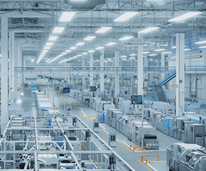
A new cell of eight presses is ordered. The machines arrive, the moulds are ready, and then somebody discovers that the electrical board is 60 kW short, the cooling tower make-up line is a 15 mm hose, and the dryers cannot fit under the mezzanine because nobody measured the ceiling. The presses sit idle for five weeks while the building catches up.
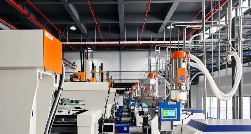
In one sentence: auxiliary equipment is every machine that supports moulding without shaping the part itself — dryers, loaders, blenders, chillers, temperature controllers, granulators and robots — and planning it means sizing power, process water, compressed air, floor space and drainage before the machines arrive. This guide covers the utility and layout side. For the equipment categories themselves, start with our plastic auxiliary equipment guide.
What Counts as Auxiliary Equipment
Six functions sit around every press, and each one has a utility demand that has to be planned:
| Function | Equipment | Main utility it needs |
|---|---|---|
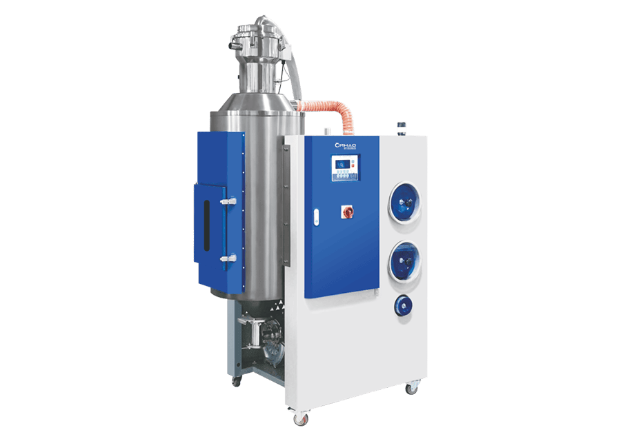
| Material drying | Dehumidifying dryer, hopper dryer | Power (heat), sometimes cooling water for aftercoolers |
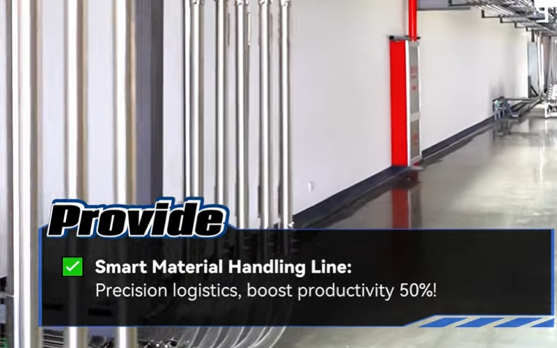
| Material conveying | Vacuum loaders, central conveying, blowers | Power, or compressed air if venturi-driven |
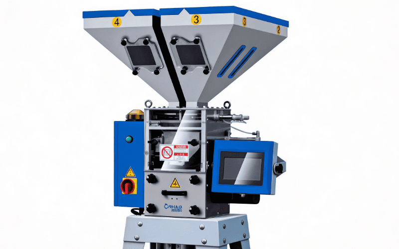
| Blending and dosing | Gravimetric and volumetric blenders | Power |
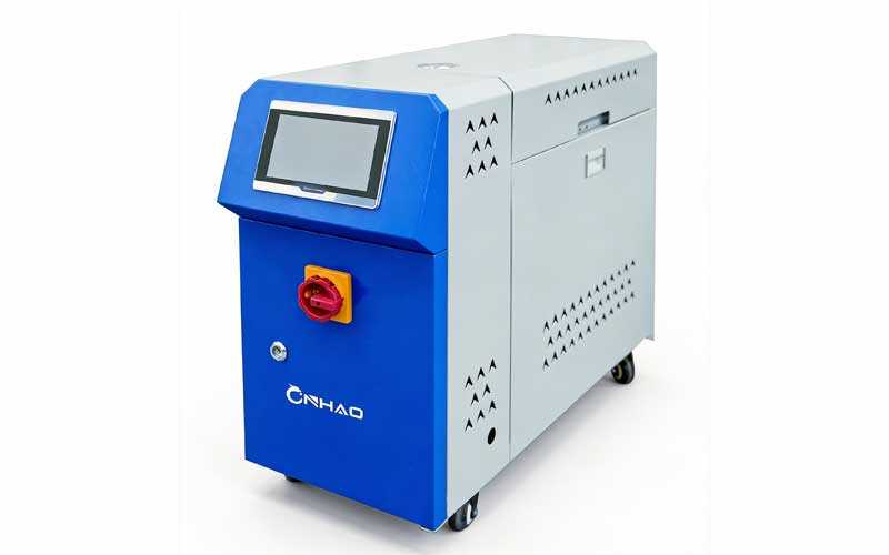
| Temperature control | Mould temperature controllers | Power (heat), water make-up |
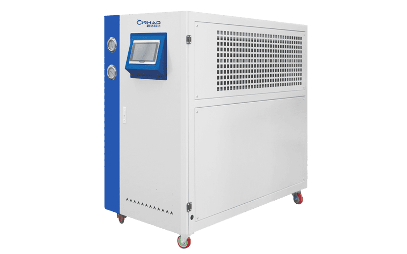
| Process cooling | Chillers, cooling towers, pumps | Power, make-up water, drainage |
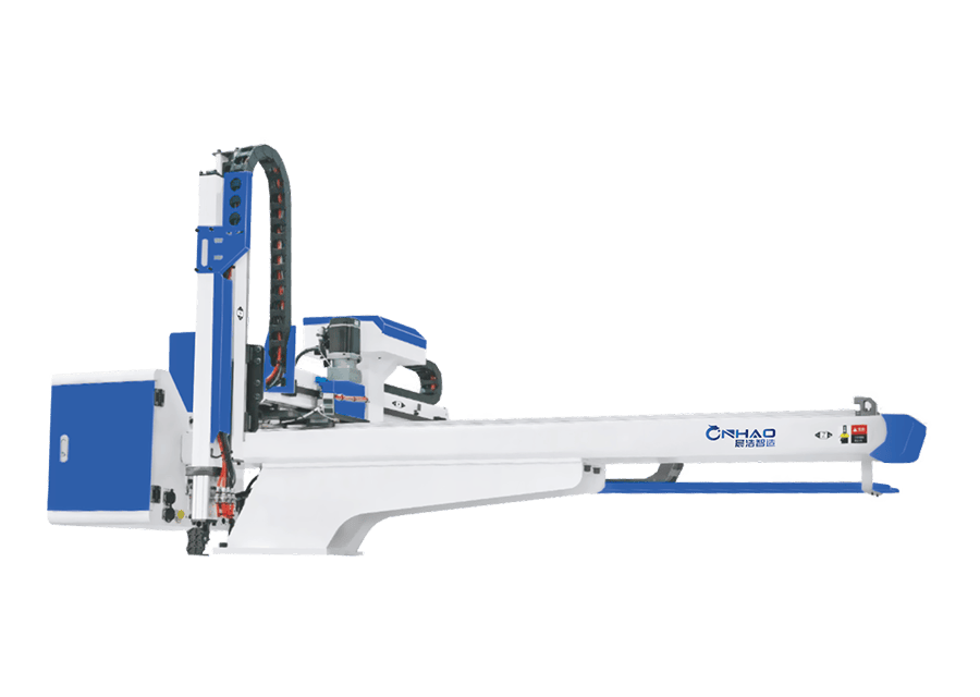
| Size reduction and take-out | Granulators, take-out robots | Power, compressed air for grippers |
The planning mistake is treating these as an afterthought to the moulding machine order. A press draws one electrical connection and one water circuit; the auxiliary equipment around it draws several of each, plus drainage and floor area that nobody has allocated.
Power: Connected Load Is Not Demand Load
Two numbers matter, and quoting the wrong one is how plants end up with an undersized transformer:
- Connected load — the sum of every nameplate rating. Useful for cable sizing.
- Demand load — what the site actually draws at peak, after diversity. Heaters cycle, granulators run intermittently, and not every press is at full output at once.
Typical nameplate ranges by machine type, for planning only:
| Equipment | Typical rating | Duty pattern |
|---|---|---|
| Hopper dryer (machine-side) | 3–12 kW | Heaters cycle; near continuous during production |
| Dehumidifying dryer | 6–30 kW | Continuous, including regeneration heat |
| Vacuum loader (electric) | 0.75–2.2 kW | Short bursts, several per cycle |
| Central conveying blower | 7.5–30 kW | Continuous while any receiver calls |
| Mould temperature controller | 6–24 kW | Heaters cycle; often 40–60% duty |
| Process chiller | 5–60 kW | Compressor cycles with heat load |
| Granulator | 2.2–15 kW | Intermittent, high starting current |
| Take-out robot | 1–3 kW | Continuous motion, low average |
Worked example (illustrative). An eight-press cell:
| Item | Quantity | Rating each | Connected |
|---|---|---|---|
| Machine-side dryers | 8 | 9 kW | 72 kW |
| Vacuum loaders | 8 | 1.1 kW | 8.8 kW |
| Mould temperature controllers | 8 | 9 kW | 72 kW |
| Process chiller | 1 | 45 kW | 45 kW |
| Granulator | 1 | 7.5 kW | 7.5 kW |
| Take-out robots | 8 | 1.5 kW | 12 kW |
| Total connected | ≈ 217 kW | ||
| Estimated demand (diversity ≈ 0.6) | ≈ 130 kW |
Size the transformer and board on the demand figure plus headroom for the next two machines; size cables and protection on the connected figure. Also budget for starting current — granulator and blower motors can pull several times rated current for a second or two, which is what trips boards that looked fine on paper.
Process Water: Flow, Temperature and Make-Up
Most plants plan chilled water and forget that water systems also consume water. Three separate demands:
- Chilled water loop — normally closed, so consumption is leakage and drain-down only. The planning item here is flow and pressure, covered in our water chiller guide.
- Cooling tower make-up — evaporative loss plus drift plus blowdown. As a planning figure, total make-up typically lands around 2–3% of the circulating flow, and it needs a properly sized line, not a garden hose. See the cooling tower guide.
- Water quality — hardness, conductivity and biological control decide whether the plate heat exchanger scales up in one season or five. Budget for treatment, filtration and a bleed line.
Then plan the drainage you will actually need: tower bleed, condensate from chilled surfaces, and wash-down water from the floor. Wet floors are also a humidity load, which is why drainage design shows up again in mould dehumidification.
Compressed Air: The Most Expensive Utility per Kilogram
Compressed air looks free because it is already in the building. It is the most expensive energy carrier in a plant by a wide margin, and auxiliary equipment can be a surprisingly heavy user:
- Venturi (air-driven) loaders — simple and cheap to buy, and they consume air continuously while loading. Over a year the air costs more than the electric vacuum loader would have.
- Robot grippers and blow-off — short pulses, but they stack up across a cell and drive the peak demand that sizes the compressor.
- Conveying valves and airlocks — small individually, continuous in aggregate.
Plan on peak instantaneous demand across all simultaneous users, not the average. Where a choice exists, take the electric option: our pneumatic conveying system guide shows why plant air is the most expensive way to move material.
Floor Space and Maintenance Clearance
Footprint is not the only space requirement. Plan for:
- Service clearance — at least 800 mm to 1 m around machines for filter changes, screen changes and motor access. Machines pushed against a wall get their filters changed late.
- Vertical clearance — the tallest item in a cell is usually the drying hopper or the dryer above it. Measure the ceiling, the mezzanine and the crane rail before specifying hopper volume.
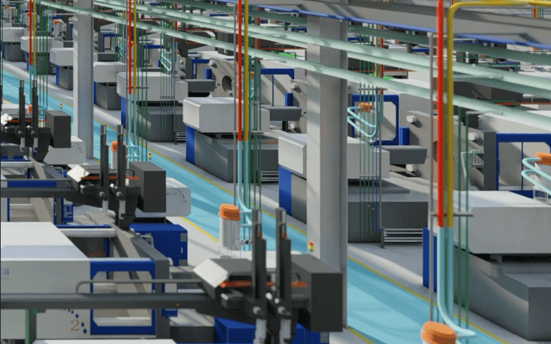
- Material flow — silo or day bin → dryer → press → beside-the-press granulator → regrind return. U-turns in that path are what create forklift traffic through the moulding area.
- Future machines — leave the pipe runs and the board capacity for the next two presses, even if the floor space is used for storage today.
One-Page Utility Summary
When you need a number to take into a design meeting, these are the planning ranges per moulding machine. They are starting points, not specifications — your resin, part weight, cycle time and climate move all of them:
| Utility | Typical per press | What moves the number |
|---|---|---|
| Electrical demand | 10–20 kW | Drying duty, mould temperature, share of the cooling plant |
| Chilled water flow | 20–60 L/min | Number of mould circuits, design ΔT, part cooling requirement |
| Cooling tower make-up | 2–3% of circulation | Evaporation, drift rate, blowdown and water quality |
| Compressed air (peak) | 50–150 L/min | Grippers and blow-off; air-driven loaders multiply this |
| Floor space | 1.5–3 m² | Beside-the-press dryers, granulators and hopper volume |
| Service clearance | 800–1000 mm | Filter, screen and motor access |
Installation Sequence
The order matters, because each step makes the next one possible:
- Utilities and drainage completed and pressure-tested
- Central conveying pipework and silo or day-bin connection
- Dryers and hoppers positioned, with drying commissioned before first material
- Chillers, pumps and cooling tower commissioned and loop flushed
- Mould temperature controllers piped to the tools
- Blenders and dosers calibrated with the actual materials
- Granulators and regrind return connected
- Robots and take-out automation taught, then cycle timing verified
Acceptance Checks Before You Sign Off
- Dew point measured at the dryer process air, under load, with a calibrated instrument
- Mould water temperature and flow measured at each tool, not read from a display
- Conveying rate measured over a timed period against the specified kg/h
- Dosing accuracy checked by weighing ten consecutive batches
- Compressed air pressure held at the furthest take-off point during simultaneous operation
- Noise levels measured at the operator position
- Spare parts, filters and screens handed over and logged
- Operator and maintenance training completed, with documentation in the local language
Seven Planning Mistakes With Auxiliary Equipment
- Quoting connected load as demand load. Oversized transformers cost money for capacity you never draw — or you under-specify and trip the board.
- Forgetting cooling tower make-up. The circulating flow is not the water bill; evaporation and blowdown are.
- Running loaders on plant air because it is already there. The cheapest capital line and the most expensive operating line.
- Measuring floor area but not height. Drying hoppers are tall; mezzanines and crane rails are unforgiving.
- No drainage plan. Bleed, condensate and wash-down all need somewhere to go.
- Zero maintenance clearance. A filter that cannot be reached is a filter that is not changed.
- Sizing for today only. Conveying capacity, board capacity and pipe runs are the three hardest things to add later.
FAQ
What is auxiliary equipment in injection moulding?
Auxiliary equipment is every machine that supports the moulding process without shaping the part itself: resin dryers, material loaders and conveying systems, blenders and dosers, mould temperature controllers, chillers and cooling towers, granulators, and take-out robots. It is planned separately from the injection moulding machine because each category has its own power, water, air and space requirements.
How much power does auxiliary equipment need?
As a planning range, machine-side drying and mould temperature control each add roughly 6–12 kW per press, process cooling adds the largest single block, and loaders and robots add 1–2 kW each. Size the board on the demand load after diversity — typically around 0.6 of connected load — plus headroom, and size cables on the connected load.
Do I need a cooling tower as well as a chiller?
If you use water-cooled chillers, yes — the tower rejects the heat the chillers remove. Air-cooled chillers avoid the tower and its make-up water but cost more per kW of cooling and reject heat into the building. The trade-off is set out in our cooling tower guide.
How much floor space should I allow per press?
Beyond the press itself, plan roughly 1.5–3 m² per machine for beside-the-press auxiliaries plus 800 mm to 1 m service clearance on the maintenance sides, and check the vertical clearance for drying hoppers before specifying hopper volume.
Should loaders be electric or compressed air?
Electric, in almost every case. Venturi loaders are cheaper to buy and run on plant air, but compressed air is the most expensive energy carrier in the plant, so the air cost exceeds the capital saving within a year or two of continuous running.
What should be on an auxiliary equipment acceptance checklist?
Measure, do not read: dew point at the dryer under load, water temperature and flow at each tool, timed conveying rate, weighed dosing accuracy, air pressure at the furthest take-off under simultaneous load, plus spares, documentation and training handed over.
The Bottom Line
Auxiliary equipment is won or lost in the building, not the machine hall. Size power on demand load with headroom, plan make-up water and drainage separately from circulating flow, keep loaders off plant air, and leave height, clearance and pipe capacity for the presses you have not bought yet.
For the equipment categories and selection logic behind these numbers, see the plastic auxiliary equipment guide; for a single-supplier approach to the whole package, see our turnkey plastic auxiliary systems.